This project was initially just an attempt to learn javascript, particularly 3D rendering in webGL to look at the 4D-Flow MRI data that makes up the bulk of my research. An early attempt at a purely client-side application can be seen here.
The rendering with three.js looked really good, so I started writing a more sophisticated server-client application that could do some real flow processing using the same visualization methods.
There is a version of this software currently running on my Digital Ocean droplet HERE, but I can't make any promises that it will still be up when you are reading this
Overview
I moved to a python server where more complicated algorithms could be implemented without nearly as much work as trying to re-implement in javascript. The main program starts a tornado server, which communicates with the client through websockets.
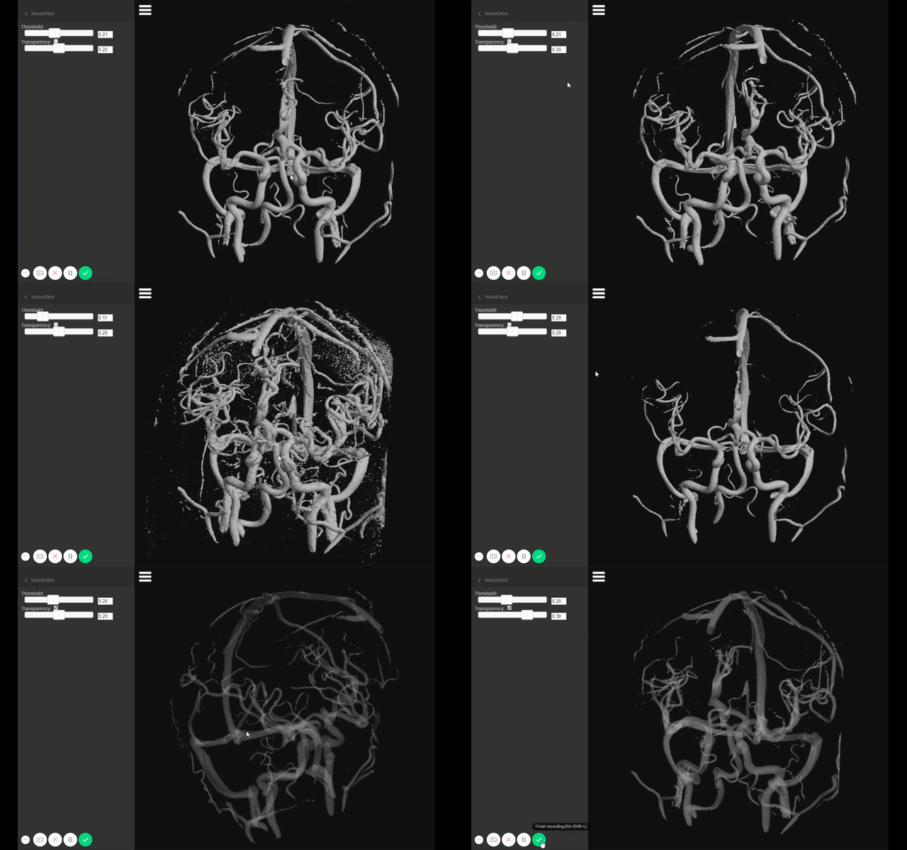
The server loads a raw 4D-Flow data set and computes an isosurface from the angiogram and sends it to the client. The client can change the thresholding for the isosurface, which requests a new isosurface from the server, allowing different angiogram thresholds to be rendered. Additionally, the three.js rendering transparency can be controlled, to better see what’s going on with streamlines.

Plane Placement
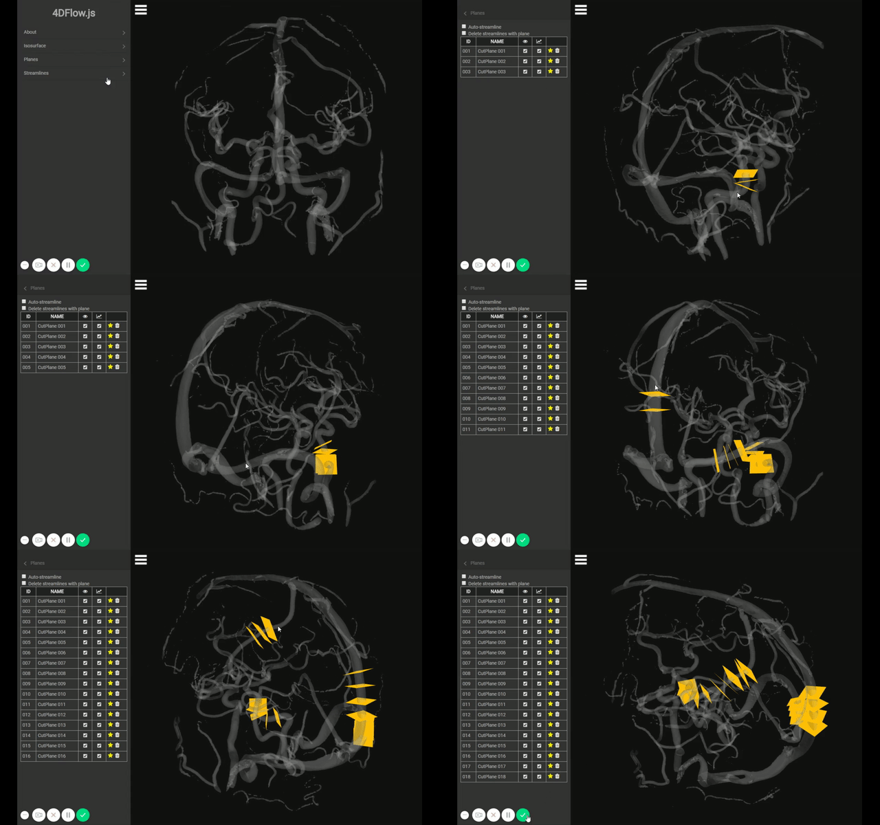
One of the biggest time sinks in analyzing this data is measuring flow rates at specific points in the blood vessels. To measure flow rates, planes need to be placed perpendicular to the vessel to be measured. This is normally done manually, which can be very annoying and take a decent amount of time.
To make this more efficient, I developed an automatic algorithm in this demo. It works by:
- Right clicking on the isosurface render
- This uses a raycasting method in three.js to find the first point on the isosurface under the mouse. We now have the vertex on the isosurface that was clicked
- The vertex and a vector normal to the vertex is sent to the server over websockets
- The normal line and vertex are used to select a point within the vessel, arbitrarily spaced from the vertex (2 voxels)
- A plane centered on this point is created. The algorithm then finds a 3D rotation that will minimize the cross-sectional area of the angiogram.
It seems to work really well, in fact I use a version of this algorithm for almost all of my flow processing without any problems.

Streamlines
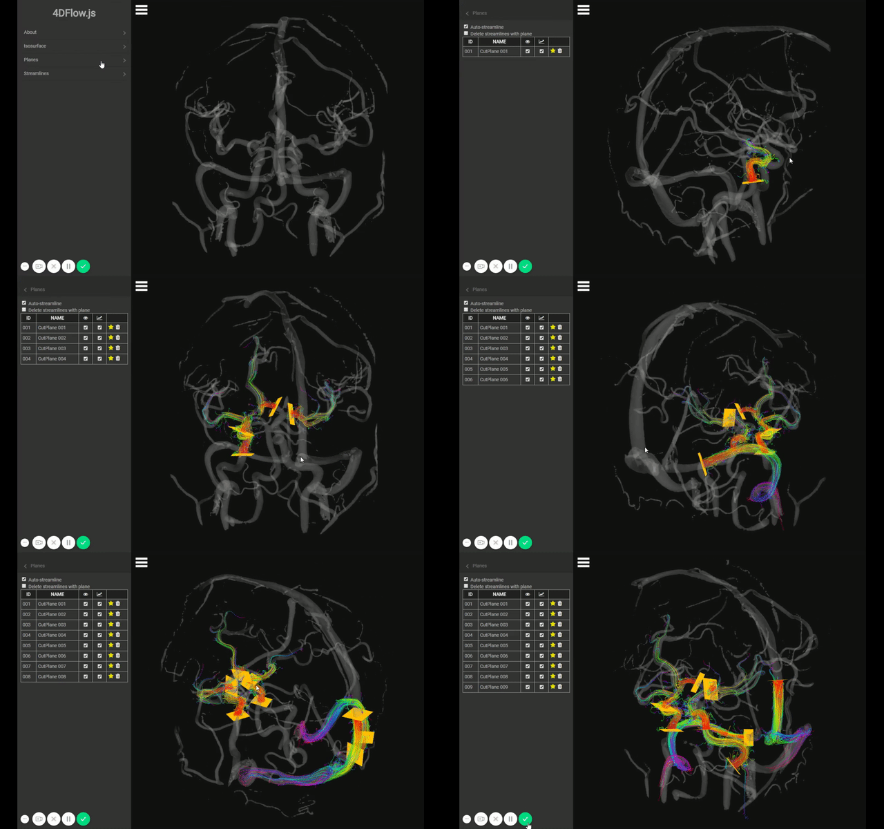
Streamlines can be generated during plane placement, where the plane is used as the streamline seed. This is enabled by checking a box in the 'planes' tab.
The client sends the request during plane creation, and then on the server a standard 4th order Runge-Kutta interpolation is used to trace the path that a particle would take in the measure velocity field. The streamlines are then sent back to the client to render. Right now, they are just colored by distance with a rainbow colormap but can be easily switched to a speed-based colormap as is normally used.

Future
This needs a lot more work to make it a fully functioning piece of analysis software, but the most immediate and useful addition is to have the automatic planes also automatically calculate flow rate. This is really easy to do on the server side because we have a surface threshold and the plane placement, the problem is deciding how to show this to the user in a useful way.
Code
As stated above, there is a version of this software currently running on my Digital Ocean droplet HERE, but I can't make any promises that it will still be up when you are reading this
The code is on github.com/mloecher/4dflow.js2
And the old outdated client-side only demo is at:
The code is on github.com/mloecher/4dflow.js